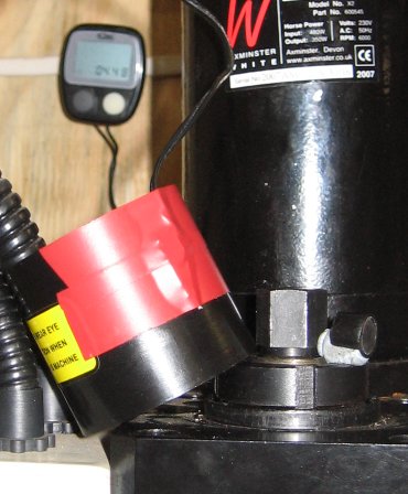
Here’s an idea I haven’t seen before. Adam made a very inexpensive tachometer for his variable speed X2 mini-mill using a cyclometer (bicycle speedometer). Almost any wired cyclometer will work and you should be able find one with a nice big display for about $15 or less. (You probably don’t want to get a wireless cyclometer because they’re more expensive, you’ll have an extra battery to replace occasionally, and you might get erroneous readings caused by the receiver picking up electrical noise from your motor).
Someone left a comment with a link to a tutorial on Instructables with more details about making one of these. The author, Jose, explains that you basically just have to glue the magnet that comes with the cyclometer to your spindle and somehow mount the sensor within about a 1/4-inch of the magnet when it spins around.
The sensor sends a signal to the cyclometer every time the magnet goes by it. The cyclometer uses that information to calculate the bike’s speed using the wheel’s circumference, which you have to tell it. In this case though, we don’t want to know speed, but RPM instead. Jose says to use 268 mm for the wheel circumference if the cyclometer displays the bike’s speed in MPH, and 167 mm if it displays in KPH.
He says those numbers will display the RPM in hundreds, regardless of circumference of the object you mounted the magnet on. I don’t why that is, even though I was once good enough at math to get an A in college calculus III. There’s a chance I’ll wake up in the middle of the night with the answer, or have a revelation while in the bathroom. But just in case I don’t, I would appreciate it if you would leave a comment with the answer if you have a good “explanation for dummies.”
The original cyclometer is a tachometer, its just doing some math to its RPM measurement before printing the number to the LCD. If we mount the magnet on the hub of the wheel, or the rim of the wheel, its still passing the sensor the same number of times per minute. And giving us the same speed reading.
The bike display is showing us:
KPH readout = rpm * 60min/hr * circumference(m) * 0.001m/km
ie if we had a 1m circumference wheel turning 1rpm, it would turn 60 rotations per hour. 60 rotations is a distance of 60 * circumference or 60m. 60 meters is 0.06km, which means the readout would show 0.06KPH.
To get a KPH readout of 1 for 100 rpm:
1 = 100 * 60min/hr * circumference * 0.001m/km
circumference = 1 / (100 * 60 * 0.001)
circumference = 0.1667m
or
circumference = 166.7mm
Congrats on a very interesting website.
A minor point: not many cycle speedos will allow you to set the wheel circumference to 166.7mm, because cycles with wheels 53mm (about 2″) in diameter are a little impractical. Better to use 1667mm, when a reading of (for example) 45.6 kph represents 456 rpm. However, if your speedo doesn’t expect you to pedal at over 99.9kph (60mph!), it may only read up to 999 rpm. My speedo thinks I’m trying for a 120mph cycling world record, because it goes up to 200kph (=2000 rpm).
Andy
Sorry Andy, but I agree with Adam and JPR’s calculations because I’ve worked out the math myself. I also bought a $12 cycling computer at Walmart that had no problem accepting a circumference of 268 mm and it works very well as a tachometer.
I haven’t finished it yet (the story of my life sometimes) but I’m working on an aluminum mount for it that will attach under my mini-mill’s head with magnets. The speedo display will be mounted on the outside and its wire and sensor will be neatly stored inside. The magnet I’m using is attached to the spindle with a couple of layers of electrical tape.
Adam’s idea is really useful if you have a CNC mill, which can be much less tolerant of incorrect spindle speeds than a manually operated mill.
I just bought a Bell F20 bike computer on eBay for $14.50. It allowed me to set the wheel size to 0268mm and units to MPH with no problems.
try the sunding SD-548C wireless
HERE YOU CAN SEE RPM ON DISPLAY.
included on cyclocomputer
http://www.ebay.com/itm/Wireless-waterproof-Bicycle-Odometer-Speedometer-SD-548-/290601362843?pt=AU_Sport_Cycling_Accessories&hash=item43a930e59b
thanks for the info. I have the bell cyclometer on the lathe with the 268mm and mph. It shows correctly up to 950 rpms than the cyclometer drops speed even though the lathe is going faster. Any ideas?
Where did you mount the magnet? If it’s on a shaft with too small of a diameter the magnetic pulses may be getting generated so quickly they can’t be counted accurately and are “getting blurred.”
I’m also wondering if the magnet could be too weak, if metal parts of the lathe could be reducing its magnetic field, or if the gap between the magnet and sensor is too big.
I went with a 12 function Bell cyclometer from Walmart and it is doing the same thing as stated above. Mine gets to 9.6mph (which if I am understanding correctly is 960 RPM) and if I go any faster it stops functioning correctly. It drops off and starts registering lower speeds. Something I noticed is a mechanical ‘click’ inside of the receiver everytime the magnet passes by it. I’m a cyclist and I don’t think I’ve ever noticed that on any of my other cyclometers. I am guessing that it is a mechanical sensor of sorts and the movements can’t keep up with higher rotations. I’ll have to try a different one.
I also picked up the bell f12 and can only get it to register up to 9.6 mph(960 rpm) I think its a limit with the switch used un the sensor…… will try another cyclometer any good ideas on brands? ??