
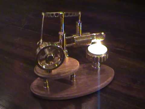
Jeroen Jonkman built this Gamma type Stirling engine for his father’s 60th birthday. He also drew a nice set of plans for it and is very generously sharing them. You can download them here from MachinistBlog (PDF) or from HMEM if you’re registered there and logged in. I asked, but Jeroen didn’t tell me much about himself. But I can tell from the videos he uploaded to his YouTube channel that he’s a skilled machinist and prolific builder of model steam and Stirling engines, many of which are of his own design. Jeroen is also Dutch and I find it interesting that two other Dutchmen, Jan Ridders and Jos De Vink, have built some of the world’s most beautiful and interesting model Stirling engines. Jeroen has not produced as many engines as those two but I wouldn’t be surprised if he does someday.
Good afternoon,
need help with engine Striling 60.
Please tell me where can I can get?
Thank you.
Hi there. The plans are missing the 2 rods which come from the Crank. One goes to the tumble plate and the other goes to the displacer rod end. Can you please send them to me. I have a couple of students who are part way through making this engine and need those parts.
I can’t send you them because these are not my plans. I would ask on the Home Model Engine Machinist Forum, which is these were originally posted. – Rob
What’s the problem? Maybe we can help. Otherwise, you’ll have to register at HMEM (see link above) and ask for assistance there.
Good afternoon rleete
Thank you very much for responding.
I would like to provide me an E-mail to send some pictures and ask what are the critical points to consider to work properly.
Both the main piston and the power piston are sealed, that is, without any leakage. Not if it is correct to give both fit and if needed give out the air by one of the pistons.
Thank you very much for the help.
I feel bad after so much work not work.
Sergio – Follow the link below to the HMEM forum and ask your questions.
http://www.homemodelenginemachinist.com/f12/plans-brass-stirling-60-a-8937/
The main things to consider for a Stirling engine are fit of the piston (smooth sliding, with no tight spots) and eliminating friction as much as possible. The power piston must be airtight, but the displacer should have clearance all around. Friction is the real showstopper. If a joint is binding, even slightly, it can prevent the engine running as they have very little power.
Also, my Stirling engine needs to warm up for several minutes before it will run. Put the heat source on it and let it sit for a minute or two before trying to get it to run. Finally, an alcohol flame will burn hotter, and may make it easier to run than using a candle.
Beautiful simplicity!
Good morning. I have downloaded the drawings of J. Jonkman’s Sterling ’60’ engine – superb clarity, nothing too difficult to machine. But I cannot find the connecting rods, displacer to crank, nor Tumbler to crank. Do I need to measure these empirically when the time comes to make them, or can I scale them off the drawing on Sheet 3/8 ?
Many thanks.
Hello, good afternoon,
I’m wondering about cylinder’s minimum temprature for the mechanism’s start to circle. I’m waiting for reply. Thanks.
Sincerely, Aziz the engineer.
Not sure of temperature, but it has to be warmed up. Mine won’t start until the flame has been on for about 30 seconds.
Even then, it has to be manually started by spinning the flywheel. A quick flick with a finger usually gets it going. As it gets hotter, it runs faster.
Hope this helps.
Hello I am building the Jonkman Stirling 60 as my first motor. Everything is clear to me from the drawings but one thing. How does the displacer rod connect to the displacer. My drawing shows the displacer with no holes in the base of it. And the displacer rod is just that, a rod. No threads. The drawings point to that area and says to solder. Should there not be a hole here for the rod to go into the base of the displacer. What am I missing here? I am sure it’s obvious to someone. But it’s not coming to me.
Your input would be appreciated
Shannon
The rod is soldered into the end of the displacer. Yes, there should be a hole in the displacer base.
Thank you. I thought so, but was unsure. Is there any reason it could not be threaded.
As well I am having a hard time sourcing some perlitic cast iron for the bearing. Could I not just use brass? If not is there another substitute?
Thanx again
Shannon
Yes, it can be threaded. I, personally, would thread it instead of soldering so that the length can be tweaked if necessary. I’d also add a jam nut to prevent loosening.
Brass or bronze are perfectly acceptable alternatives for the bearing. You could also use graphite, but that may be harder to find than the cast iron. About the only thing not to use is steel, as the shaft is steel and galling may result. If you use brass for the shaft, you could use steel for the bearing.
Thank you sir.
another question. Just want to double cheque as I am two hours from city any going there tomorrow. In the prints for the candle holder. It says the radius on the cuts for the around the edge is R5. Would that be a 10mm ball end mill then?
Yes, that would be correct. 10mm is pretty close to 3/8″, so that would work.
As those features are purely decorative, it is in no way critical. You could use any size that looks good to you. Heck, you could even knurl it and it would be okay.
Same question as Terry Froggatt already asked one year ago (without getting an answer)…. where to find the dimensions of the connecting rods, displacer to crank and Tumbler to crank?
Thanks, Hans
Try joining HMEM and posting the question there. The original designer may be able to clarify, or other members who have built this engine.
I have just finished mine and it goes like stink, amazing.
A few observations.
Friction is a killer as has been said before, the mechanism needs to spin freely with no tight spots.
Take care to only use Pyrex test tube material, borosilicate is useless and will crack. Getting the tube to engage with the inner o-ring is a pain. I cut my tune down with a Dremel type diamond cutter and ground a bevel on the open end to help the tube to slide inside the inner ring.
I made all the connecting rods the same way. Use 6mm brass rod for the end clevises and 2mm silver steel cut to length for the bit in the middle. It is easy to fiddle with the rod to get the right length and then secure it together with Loctite.
I used 2mm silver steel rod for all the pins and bearings.
For the displacer I used aluminium as it is easier to turn to a thin wall, and it has a higher thermal capacity than brass. I used 3mm silver steel for the displacer rod and screwed it into the displacer end block. There is no need for a CI sleeve inside as a guide for the displacer rod. I extended the back of the displacer housing to increase the bearing surface and improve the air seal.
Loctite works wonders.
Good luck.
Jeroen Jonkman’s “Stirling 60″ The Pyrex test tube, where can I get hold of them? Dose anybody have some I can buy.
Thanks
Keith
I have spare pyrex tubes, how many u want?
More on this. My first effort I made the power piston 1/4″ dia as I alredy had some silver steel handy. It worked ok after a lot of hassle to reduce friction. The Teelights also soot up the pyrex tube so I made a small spirit burner, it worked much better with the increased heat input going several hundred rpm.
After a bit of reading up I find the power piston is too small in relation the the size of the displacer. I made a new cylinder and hollow piston 12mm dia and this goes like stink. I reckon enough power to drive a small genny. All good fun!
Hi I am Robert
I would like to know how you make the displacer? It is very tin and round at the end is it press from a sheet of metal or machine to me it to tin.
Thank you
Robert
Does it make any difference if the hole engine is made out of Stainless steel (AISI304) or AISI 316.
Does it run as good as brass?
I mean Stainless steel is not as fast with the heat as the brass or bronze…
Stainless, while harder to machine, will work just fine. The original designer uses the same materials for almost all his engines, but notes on his website that others may be substituted. For these small engines, the differences in running will be very minor. I would guess that the most noticeable difference would be that it takes longer to heat up.
Can a used CO2 cartridge be used instead of the test tube?
Unlikely. You need a perfect low friction fit and I think it’s unlikely you could get that from a cartridge. Glass test tubes can be purchased cheaply on eBay or Aliexpress. You can easily cut one by buying a small rotary diamond cutting disk from Harbor Freight for $6 and mounting it on your lathe’s tool holder. Keep the glass wet with water or rubbing alcohol while cutting it.
I will cut a cartridge and measure it for roundness and taper. If there are any variations I will correct them. I would not be able to do that with a test tube. To absorb more heat from the flame maybe fins covered by a thin shroud (litho?) could be formed with a vent on top.
Can anyone advise me on where I might purchase the thin wall pyrex test tubes?
Best prices are on Amazon or eBay. Also available from chemistry supply places like Fischer Scientific, but I think you have to buy in case quantities (500 pieces?) to place an order.
Also, while the pyrex ones are more durable, plain old borosilicate glass ones work quite well.
This YouTube video shows a recent (2019) build of this engine and the builder just answered someone’s question about its construction. So he may be willing to answer your question.
https://youtu.be/9GmeTrotHZg
I don’t know if it’s still active, but at one time you could find a lot of info about this engine in this forum discussion:
http://www.homemodelenginemachinist.com/f12/plans-brass-stirling-60-a-8937/
Regardng the power cylinder. The 5mm hole goes all the way through correct?
Yes thats correct 🙂