This tutorial was written by Earl Hackett, who graciously gave me permission to republish it here. Earl found that even though his mini-mill was trammed correctly, different length drill bits were not hitting the same spot on the work piece. He found that the spindle was slightly tipped and tilted instead of being square with the column. This article will tell you how to test your mill to see if it has the same problem and how to fix it if it does.
One of Earl’s interests is model railroading and he is modeling the Chesapeake and Ohio Railway as it was in 1952. He uses his mill to make molds for small parts that he vacuum casts in epoxy. He often uses very small cutters (ex. .007-inch) so his mill needs to be precisely aligned.

A nagging problem had been present since I first purchased my mini mill. After marking a hole with a spotting drill, I would switch to a jobbers length bit to drill it. When the jobbers length bit made contact with the work piece, it would be noticeably to the left of the original mark. This could only be explained by the spindle not being aligned with the column. The spindle casting is mounted on the ways casting with 4 cap screws. There is no alignment guide so the spindle casting can rotate through a small arc. It was an error of only 10 or 15 mils so most metals were strong enough to pull a jobbers drill bit into alignment with the pilot or spotting hole. However, when machining soft materials such as waxes or plastics the jobbers drill would not bend to the correct location and the hole would not be in the desired location. So while the mill was disassembled for installation of a digital read out, I decided to correct the problem.
The first step was to place a straight shaft (McMaster Carr – ½” ceramic coated aluminum, 15″ or longer (1031K14, $9) in a collet and make sure it is mounted on the axis of the spindle. A tiny piece of dust on the mating surfaces will knock it out of alignment. I checked this by measuring the runout as far from the collet as possible. The best I was able to achieve was ±0.002″ about 9″ from the collet.

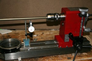
With the shaft aligned the next alignment was with the table’s Y axis. The 4 mounting bolts were made snug, but not tight. A dial indicator was placed on the top of the shaft as shown in Photo 1.
I turned the shaft so the indicated runout was at the mid range and the head was run along the column. On my mill, the indicator showed a movement of about 0.004″ over 8″ of travel. A 0.002″ shim at the top of the seam where the two castings join brought the deflection to under 0.001″.
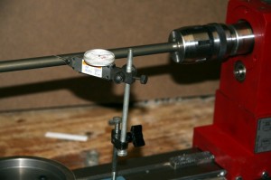
Next the indicator was mounted to measure the error parallel to the table’s X axis as shown in Photo 2.
Again the shaft was rotated to the midpoint of the indicated runout and the head moved along the column. The indicator showed about 0.016″ deflection over 8″ or 9″ of travel. I simply twisted the head until the deflection was less than 0.002″. The head was then run to the top of the column until the two upper bolt heads were exposed. These were tightened and the alignment was checked again to make sure it didn’t change. The head was then removed so the two other bolts could be tightened.

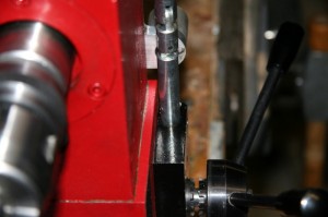
The variation in the width of the gap between the original paint and the body in Photo 3 shows the error that was present in the as received condition.
Someone read Earl’s article, fixed their mill and then started a nice thread with lots of pictures over at the Home Model Engine Machinist forum:
http://homemodelenginemachinist.com/index.php?topic=6007.0
Pictures have been changed from what they should be to an incorrect link.
Charles,
I found a bad link to one of the discussion groups but the links to the pictures seem to be OK. Could you be more specific? I appreciate your help with finding errors. – Rob