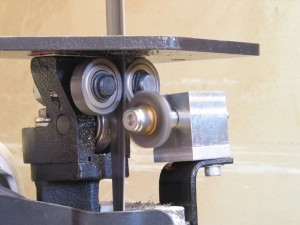
 This article was written by “Mikey” and it first appeared on the Yahoo 4x6Bandsaw discussion group. I think it is a great idea and well presented so I asked him if I could republish it here and he graciously agreed. It originally appeared as a PDF file that is formatted better and has larger pictures that you can download here. — Rob
The Jet HVBS-56M is a capable saw for home use. Quiet and powerful, this saw is quite accurate once it is properly adjusted. Like most saws in its class it isn’t the perfect saw in that the supplied table for vertical cutting is inadequate, it uses an imprecise spring mechanism to control down feed, and it lacks a chip brush.
This last deficiency, the missing chip brush, is the subject here.
Every blade manufacturer advises that a chip brush is important to the longevity of the blade and the machine so this really should be addressed on our saws. I mean,… “how hard could it be?”
A net search revealed surprisingly little on this subject on this class of saw. I had some questions that needed answers:
- What does a chip brush actually do? Yeah, I know it knocks off chips but what is the actual functional result of this action? Is this result important enough to make me design and build a brush?
- Is a static wheel as good as a moving wheel? If the latter, how can the wheel be driven?
- What material should the wheel be made of – steel, brass, plastic? How big a brush do I need?
- If a single wheel will do the job, will two do the job twice as well?
- Where is the wheel best located? On my saw, where is it even possible to mount a brush?
- How do you actually adjust a chip brush?
I was not able to find most of the answers to my questions on the net BUT I was able to look at some different types of brushes that could aid in design. What I hope to do here is answer some of the questions above, at least to the extent that someone can decide whether to build a chip brush or not. I suspect a lot of 4X6 owners must have entertained the same questions.
So, what does a chip brush actually do? It knocks chips off the blade as it passes the brush, the result of which is to reduce the amount of re-cutting the blade must do. This cleaning action is thought to reduce stripped teeth, premature wear of the blade, chip welding to the teeth and rough cuts.
Which of the many types of brushes will be the most practical and effective on this saw? A static brush, one that just bolts in place and is rotated as it wears, is the easiest and cheapest to build. It is the type Jet uses on its next higher class saw and would suffice in the home shop. However, a rotating brush is almost as easy to build and is more effective at chip removal. I tested a static and rotating brush to see which removed more chips by catching as many chips as I could in a tray while cutting 12L14 steel. My eyeball meter suggests the rotating brush removed about a third more chips, probably because the chips are thrown out by centrifugal force as opposed to packing into the wheel on the static brush. Hardly scientific but over the many linear feet the blade will run I think it is reason enough to make a rotating brush.
Obviously, a motor-driven brush is out of the question on this class of saw, which leaves only a blade-driven brush. This means the brush is rotated by the blade as it passes across the brush. Accordingly, and in the interest of longevity, ball bearing supports would be called for. These bearings should be a sealed-type bearing given the environment in which they will work.
As to which type of brush is best I found no answer to this on the net. Plastic would work but not for long. Brass is soft and may wear the blade less but longevity is a concern. For all practical purposes, then, steel is the answer. Fortunately, they are also readily available and cheap. As to size, the contact patch is very small so the smallest brush of reasonable quality will work – a 1″ diameter wheel with a 1/4″ arbor hole seems to work well. There are fine and coarse wire wheels; I only tested the fine wheel and it will serve.
How many wheels do I need? On large industrial saws one often finds a two-brush, motor-driven design. The brushes flank the blade in an area where the blade runs straight. On the Jet such a place is hard to find. I found no information on whether a two-brush is better than a single brush so I built both and found that the two-wheel version didn’t seem to clear chips any better than a single brush. Moreover, it was very difficult to align the two-brush version because the blade curves in the only area where placing such a brush is practical.
Where can I put the thing? Locating the brush is feasible in only one place on this saw- just under the lower blade guides. Here, it is out of the way of the cut and the saw’s body, clears chips at the earliest opportunity, and there are holes for a mounting bracket already located there. The brush can be positioned so that the tiny amount of pressure it puts on the blade is countered by the thrust bearing that backs the blade in the only location where the blade is still running straight.
So, we need a small, cheap, easy to build single fine-wheeled chip brush that is blade-driven and ball bearing supported, located just under the lower blade guides.
Here is my example:
I have not seen one like this anywhere, though it is simple enough in concept that I’m sure it has already been built by someone.
Materials used:
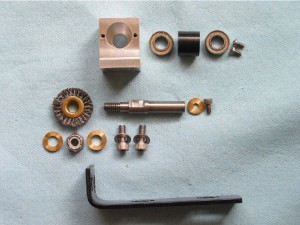
- Wheel: Osborn 1″OD fine steel wire wheel, 1/4″ mount. Up to a 2″ OD wheel will just clear.
- 2 Teflon sealed, permanently lubricated 8mm bore x 16mm OD x 5mm wide bearings from VXB Bearings on Ebay. These do not have a number stamped on the housing.
- 1″ x 1″ x 1″ T-6 bearing housing.
- 0.374″ OD mild steel shaft. There is little stress on this part so mild steel works fine.
- Mild steel strap support.
- You will need a lathe, a 4-jaw chuck and associated tooling.
Construction Notes: this will vary depending on which bearing you use but the general process is the same.
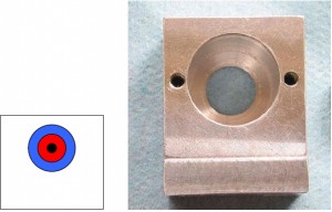
1. Square the housing block and lay out the bearing location. I chose to leave a 0.125″ space above the bearing. Center punch the bearing center mark and offset it in your 4-jaw chuck. (Note: if you don’t have a 4-jaw chuck just cut your block oversize and bore it in a 3-jaw, then mill to your dimensions.) Drill a through hole slightly larger than your main shaft diameter. Measure your bearing OD, then bore the hole to leave 0.125″ of material at the bottom of the bore, and then bore a shallow (0.005″) clearance bore into the bottom to clear the diameter of the inner bearing race. Keep the main bore clearances fairly tight, on the order of 0.0002-0.0003″, so the bearings don’t rock.
2. Drill and tap for two mounting screws under the housing. These will lock the housing to your mounting strap/bracket. (I found offsetting the block in the chuck to bore the bearing hole left me with only 0.25″ of material in which to drill and tap holes for mounting. I decided I wanted more thickness so added a 0.25″ spacer, screwed it to the block, then drilled and tapped for 10-32 screws to lock it to the steel strap support. I should have followed my own advice and made it oversized and then milled the top.)
3. Slip 2 bearings into the bore and measure from the outer race to the rear of the housing. Make a spacer (I used Delrin) to separate the bearings, which will bring the outer race of the rear bearing flush with the rear of the housing. Drill a through hole in the spacer larger than the inner race, then turn to fit the bore and cut off.
4. Determine how you will secure the bearings in the bore. I used the heads of two 4-40 screws but a cap of some kind would also work.
5. Make the main shaft.
a. Measure the distance from the center of your blade to where you want the front of the housing to be; this will be the center of the brush. Leave enough stock on either side of this mark to allow for the locknut, spacers, brush and the section that runs through the bearing housing, then cut off.
i. To keep things simple I turned the portion that runs through the bearings first and was able to more precisely determine dimensions of the portion that held the brush, so cut off longer than you think you will need and we’ll fine tune it later.
b. Turn the section that passes through the bearings. You want this to be a fairly good fit, on the order of a few thousandths only. Be sure to leave a square shoulder where the shaft steps down to enter the bearings so the entire shoulder engages the front inner bearing race. Cut off the turned section, such that the end of the shaft just clears the outer race of the rear bearing. This will keep
the shaft tight and the brush from wandering.
i. If you cut off too short (don’t ask), just take a little off the shoulder on the other end with your cutoff blade to get your required clearance.
ii. Drill and tap for your screw of choice (a 6-32 works well) on the end of the shaft, and remove the shaft from the chuck.
iii. Make a washer to pass the screw, with an OD the same size as the inner bearing race. When the washer and screw is in place the shaft, spacer and bearings will become one assembly. Lock this into the housing with the two 4-40 screws and again measure to get the dimensions you will need on the brush side of the shaft.
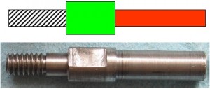
c. Re-chuck the shaft and cut the nose of the shaft so it can be threaded. I used a 1/4-20 threaded section 0.625″ long so that I could fine tune the brush’s location with spacers. I also left a 0.500″ section of unturned shaft behind the threaded section, the end of which is the shoulder left as the shaft steps down. Note that this results in about 0.125″ projecting into the housing and contacting the inner race of the front bearing. If the OD of your shaft is close to the hole’s ID then the amount of chips that can reach the bearings will be minimized.
d. Now mill or file two flats on the section between the brush and front of the housing, on opposite sides of the shaft. This provides a surface for a wrench to fit so the locking nut can be tightened.
e. Any spacers or washers needed to mount the brush can be made once the brush housing is mounted in its final position. Mine are brass and position the brush so the nut just flushes to the end of the main shaft.
This completes the brush assembly.
6. Now make the mounting bracket. As your saw may differ from mine you will need to determine how to mount the brush. Try to leave enough vertical and lateral adjustment to position the brush so that the center of the brush aligns with the center of the thrust bearing, and some rotational adjustment so the brush can run in line with the blade.
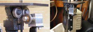
To position the brush in the right place I raised the brush so the contact point is centered on the rear thrust bearing when viewed from the side. Here, the blade runs straight and the brush contact is flush across the width of the blade. The brush is brought in until it just turns constantly when the blade runs. There is just enough pressure to keep it turning whenever the saw is on but I can stop the brush with just light fingertip pressure on the rear of the shaft. This position allows the brush to do its job while minimizing wear on the brush and the blade.
Does it work? This is difficult to measure but it appears to work very well. The cut surfaces are smoother, there are very few chips on the upside of the cut with all materials, and there is almost no discernible heat in the stock held in the vise according to my digital (finger) thermometer. In my opinion, it works.
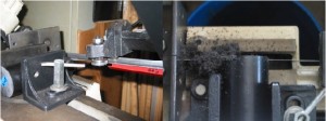
Delrin is the messiest stuff to cut. In these shots the blade is running, with very few chips on the upside of the stock.
Only time will tell if the brush extends the life of this blade but if the blade manufacturers are right then this little accessory will serve me well for a long time. As there is little stress on the bearings I doubt they will ever require replacement. The brush will also last for a very long time due to the minimal contact it has with the blade and because the wear is distributed over its entire circumference.
The cost for the entire project was less than $5.00 for the brush and bearings; the stock was scrap in my shop. (I’m actually lying — to get two bearings you ‘gotta buy 10 of ’em for about $10.00. The brushes cost me $8.00 for 2 dozen of them. Still, it’s pretty cheap to make this thing.)
I hope this helps you decide whether this accessory is worth building. It is an easy project for any HSM and as simple as I could make it.
And it works.
Mikey
September 10, 2009
Thats what i was looking for a long time. I have to make a presentation at a congress in germany and this informations was what i need. Thx a lot.
Glad it helped, Knapp. Have a good trip.
Mikey
I Love this Article! Thanks a lot!
You’re welcome, Bradley. I hope it helps. I love this little brush. I am using the same blade I had when I wrote this article and it is still sharp and cuts very cool and I’m pretty sure this brush is partly responsible for the longevity of the blade.
Mikey
Where did you buy the brushes for this chip removing project?
I bought mine on ebay. They are 1″ diameter fine wire wheel brushes with a 1/4″ arbor hole. You can buy them at McMaster Carr and other suppliers. If you absolutely cannot find one let me know.
Mikey
Thank you for taking the time to put together an excellent article. Your modification looks like a good idea that is well executed. Nice work.
Thanks, Kglesq. I hope it helps sort out your thoughts on making one.