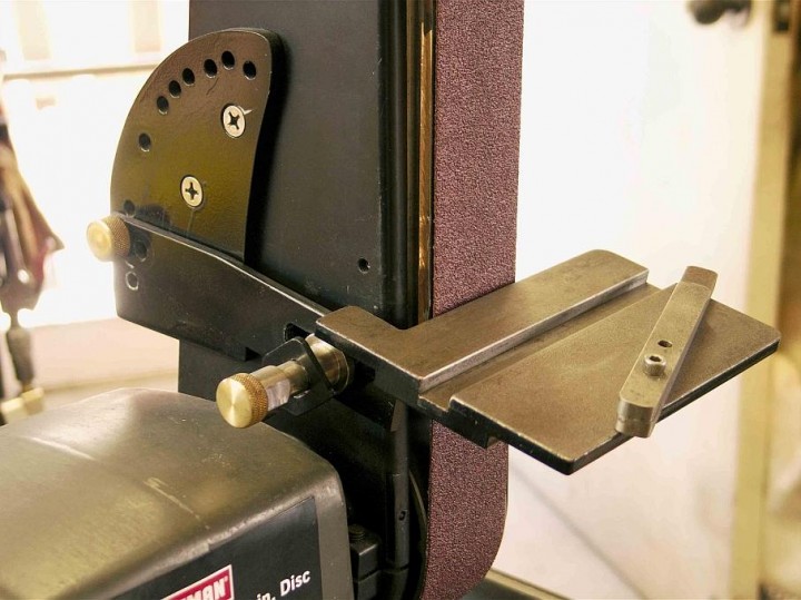
 The Craftsman 2 X 42-inch belt sander is a very good general purpose belt sander. With its 1/2 HP motor it can handle most light duty work in the shop, including grinding lathe tools for both metal and wood lathes. This grinder allows for very fast belt changes, tracks well with a simple adjustment and has enough power to grind tools without overheating or bogging down. However, it does have two deficiencies that must be addressed before any serious grinding can be done on it — the main grinding table and the platen.
The OEM table is made of cast aluminum. It pivots on and locks with a single large screw. Firm pressure on the table can overcome this screw and the table will move with the belt running, which is very dangerous. My advice is to dump it and build a decent table.
The OEM platen is stamped mild steel. It is okay for light use like shaping Popsicle sticks but will not last long grinding lathe tools. The platen is mounted solidly to the chassis and is fairly stiff but pressure on the belt will wear a divot into it quickly so basically it’s useless once this happens.
Resolving these deficiencies isn’t difficult but it requires some fabrication. I’ll show you how I addressed them.
The Platen Fix
A grinder platen has to be solid and unyielding, flat and ideally long wearing despite driving a grinding belt and grit over its surface. No steel platen I know of will withstand this kind of abuse for long but a ceramic glass liner will. This liner is actually a high temperature glass material originally developed by Corning and is commonly sold by knife making suppliers in 2-inch wide X 1/4-inch thick slabs of varying lengths. Commonly known as Pyroceram, it is usually mounted to a steel backing plate with JB Weld. This stuff is highly wear and heat resistant and only a full-time knife maker is likely to ever wear one out. If you do no other mods to your grinder at least do this one.
I used a 2-inch wide X 9-inch long X 1/4-inch thick piece of O-1 precision ground steel as a platen/backing plate because I wanted a flat mounting surface that would not move with heat over time. I know that mild steel can move with localized heat and while this may not break the epoxy bond … it might. So far, I have had no separation issues so this worked for me.
I drilled and tapped two 1/4-20 holes on each edge so the platen can be flipped over if the liner ever wears on one end A piece of 1/8-inch thick X 1.5-inch wide angle iron (not aluminum) is used to attach this backing piece to the side of the chassis using the OEM screws and platen mounting holes. The mounting holes in the angle iron are slotted to allow squaring of the platen to the belt. Offset your platen and chassis screws if you copy this; the way I did it works but it would be better if the screws were clear of each other.
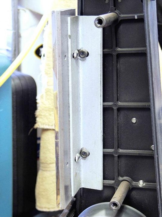 Before attaching the liner to the platen, be sure to lightly bevel or round the side edges of the liner and more generously round the top and bottom edges to prevent cutting the belt. This is best done on a slack 50-60 grit belt. The sparks will be orange and the glass will glow but it grinds easily enough. I also lightly sanded the side of the glass that would bed in epoxy using sandpaper overlying some plate glass to give the glass some tooth.
I put some oil on the tip of some 1/4-inch screws and use nuts to lock them down with their ends just flush with the epoxy side of the steel platen. This is to keep the holes clear of epoxy. After cleaning both contact surfaces with lacquer thinner, a 2 X 9 X 1/4-inch piece of Pyroceram is bedded onto the face of the platen with an even layer of JB Weld. I covered the face of the glass with a thin piece of plywood and clamped it with 4 spring clamps and allowed it to dry for a full 24 hours. JB Weld has the highest heat tolerance of any commonly available epoxy, at least to my knowledge. Ideally, you want to have a ledge under the glass liner to keep it from being knocked loose but mine has been stable for many years without a ledge. Be sure to use blue Loc-Tite to attach the platen to the grinder chassis so it won’t vibrate loose but can be easily removed if needed.
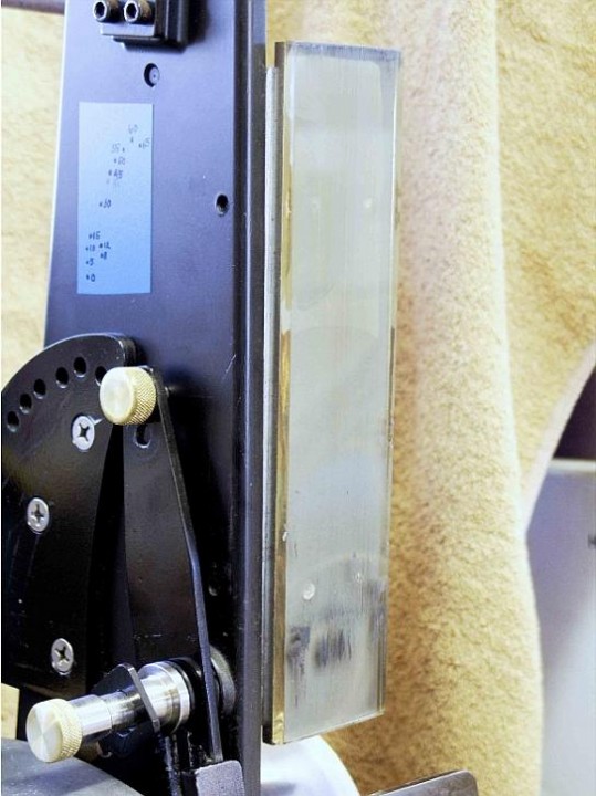 In use, the Pyroceram platen is used like any other platen. Since it is glass you should avoid slamming hard objects into it but otherwise it is tougher than nails. I have ground hardened steels, tools, and other assorted materials and have yet to see any indication of wear or movement over the years, though the picture shows some transfer of paint from the back of the belt. Pyroceram is some truly amazing stuff. The piece I used cost $20.00, delivered!
The Table Fix
Whichever table design you choose it must be quickly set to precise and reproducible angles, lock solidly so it cannot move under pressure, and should be made of steel to resist wear and heat. Having a protractor slot is optional but is very handy for some grinding operations. This one meets all these criteria.
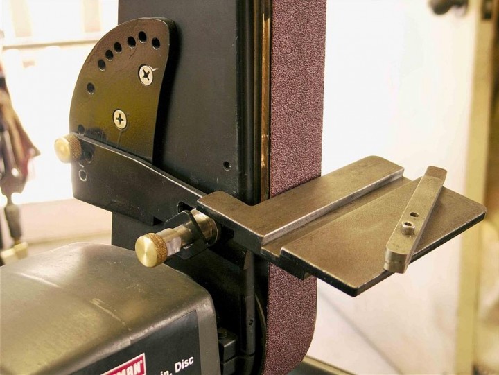 My table design was developed in my shop almost 10 years ago after seeing an indexing accessory in a book on machining. This came at a time when I was trying to figure out how to index and lock the table reliably. This design relies on a locking pivot at the front and a pin at the rear that can be indexed into precision-drilled holes in a chassis-mounted template to allow very fast and accurate angle changes. It is absolutely solid. My initial design included template angles from zero to 45 degrees but I got into wood turning over the last few years so I expanded the range. Note that the current shape of the template simply follows the swing of the arm as it moves from zero to 65 degrees of table angle.
I mention the above because there is now a grinder being sold by a well-known UK wood lathe tool maker with an almost identical setup! I developed this one independently and, I think, first. In any case, it is now a commercial product. I do not know if it is patent-protected so you shouldn’t copy this idea and sell it. You can copy mine for your own use only. The commercial product does have one feature that is better than my original design — the locking screw uses a captured wrench that is so simple and efficient that I adapted it for use on my machine when I saw it. I have seen this captured wrench idea elsewhere so it’s not original but I can’t recall what the application was. In any case, keep it in mind for when you need a simple tool-less locking screw.
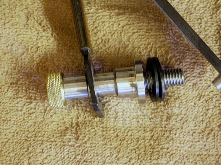 This locking screw is made of stainless steel with a knurled brass cap and a 10mm stainless metric screw on the other end. A Delrin washer goes on either side of the table arm; the inner one is sized to bring the inner surface of the arm flush with the template. There are four non-critical diameters to the main body; from the inside they are: 0.942, 0.625, 0.482 and 0.600-inches. Don’t bother duplicating these dimensions; I just cut ’til it looked good to my eye. The length is also non-critical; this one is 1-3/4 inch long with a 1/4-inch thick cap so is 2-inch in overall length. The outermost diameter near the cap has two flats milled on opposing sides; width at that point is 0.585-inches, also non-critical.
The wrench is made of flat 1/16-inch thick steel and is 2-1/2-inch long. It has a hole that matches the profile of the outer diameter, including the flats, and is free to slide. I made this by milling the slot and hand filing it to fit. In use, it can bear on the flats to lock or unlock the screw, and then be moved to the center section where it is free to spin or rest. The brass cap serves to rapidly turn the screw or remove the wrench at need. Since this screw only has to lock the table to the chassis of the grinder it does not require a lot of torque; a small wrench is more than adequate for this purpose. It is an ingenious design — simple, effective and does not vibrate loose.
The table itself is made from 3 pieces of 2-inch wide X 1/4-inch thick mild steel flat bar, about 5-1/2-inch long. The bottom piece has three 3/8-inch holes drilled into each side and the top two pieces are rosette-welded to the bottom piece through these holes, trapping a 1/2-inch bar between them to form a slot. I wrapped the 1/2-inch bar with a single piece of paper to give the protractor clearance so it slides even when there is a lot of grinding dust on the table. The inside part of the top is shaped to provide a support ear on the left side of the belt; do this before welding. The outside end is left straight so belts can be changed without moving the table.
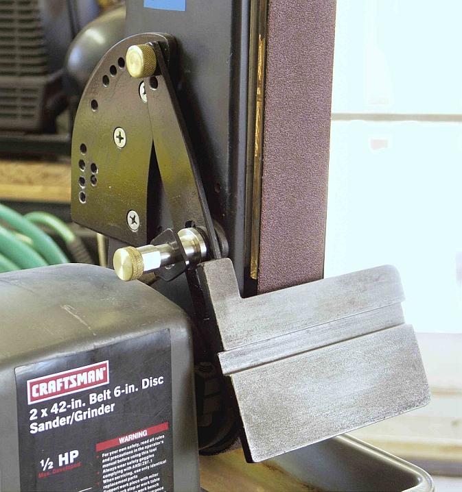 A 6-1/2-inch long X 1-1/2-inch wide X 1/4-inch thick arm is welded to the bottom of the table; it locates and bears the pressure on the table in use while the locking screw simply holds the arm in place. The forward end has a 1-1/2-inch long slot that fits the locking 10mm screw; this allows the table to be moved fore and aft to keep the edge of the table close to the belt at any angle.
There are two 3/8-16-inch tapped holes on the other end of the arm. Spacing between the holes is 1/2-inch; they allow the indexing pin to be moved to accommodate close table angles, such as 10 degrees, 12 degrees, etc. The 10 degree hole will use the outside pin position, while the 12 degree hole will use the inside pin position, and so on. The tail of the arm is aesthetically tapered, at least to my eye, and then the arm is welded to the bottom of the table.
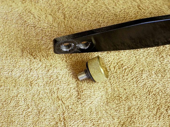 The pin itself is a 3/8-16 SS screw threaded into a knurled brass knob. The end of the screw is turned down to 1/4-inch OD. When in position only the 1/4-inch pin projects from the back of the arm. A Delrin washer rests between the knob and the arm so the pin can be moved easily, even with grinding dust in there.
The pin fits into holes in a chassis-mounted template that has holes drilled to index the table to pre-set angles.
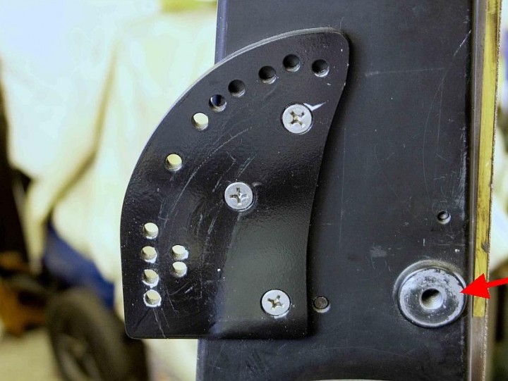 To make this template, I clamped a piece of 1/4-inch thick mild steel plate to the chassis with the bottom edge 1/2-inch below the center of the locking screw hole. The template was marked and drilled for three 1/4-inch mounting holes. The chassis was marked through these holes with a transfer punch, then drilled and tapped for three 1/4-20 flat head screws. The template was then countersunk for these screws.
With the template mounted solidly to the chassis I put the table in place and used a digital protractor with a magnetic base to level the table; the inside upper edge of the table is placed 1/8-inch away from the belt at all table angles with a spacer. With the table now at “zero”, I removed the belt and used a machinists square to align the platen at 90 degrees to the table. The belt was put back on and remained there so the table-to-belt spacing was consistent. With the table locked at the pivot and the arm at the rear clamped to the template, a transfer punch was used to mark the zero setting on the template through the outer hole in the arm. The clamp was removed and the table was moved to 5 degrees using the protractor; spacing was 1/8-inch to the belt, and another hole was marked. In similar fashion, holes were marked for angles I commonly use for tool grinding: 0, 5, 8, 10, 12, 15, 30, 40, 45, 50, 55, 60, and 65 degrees. The holes for 8 and 12 degrees were marked using the inner hole in the arm as there is no room in the outer row for these holes. Once all holes were marked the rim of the template was marked to follow the arc of the arm. The template was removed, the holes were drilled and reamed to 1/4-inch, and the template outline was cut and ground to shape.
In use, the locking screw is loosened enough to slip the indexing pin into the desired hole, and the locking screw is tightened. This only takes a few seconds. If I need to use a table angle for which there is no hole in the template I simply set it with the digital protractor and use a clamp to lock the end of the arm to the template. This setup has proven to be absolutely solid, repeatable, reliable, and very fast. It takes some time to make but it worth every second spent.
If you build this table be sure to paint your parts to prevent rusting but leave the table top unpainted — wax and/or oil will keep it serviceable.
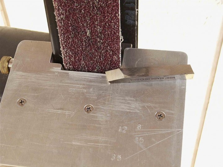
When grinding lathe tools there must be support on the right side of the table for the bit. I built an auxiliary table that drops onto the main table. It is located by a steel bar attached to the bottom of the table that fits in the table slot. The table is just a piece of plywood with an aluminum top, shaped to provide support all around the belt. I scribed some commonly used back rake angles on the right side of the table. In use, it just drops on or pops off in a few seconds and works very well. It also allows for belt changes without moving the table.
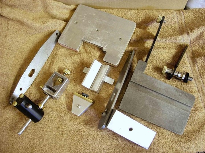
 Numerous accessories can be made to grind other tools, especially wood turning tools. I mimicked the designs of multiple commercial devices and adapted them for use with my table. They allow you to sharpen almost any wood lathe tool in existence with precision. Since they are made from stuff already in my shop they cost only the time to make them. I show them below but will not bother to describe them — they all work extremely well.
 I also use a protractor in the table slot on occasion. It is simply two pieces of 1/2-inch wide X 3/16-inch thick mild steel bar that is milled flat on all sides; one is 4-inches long and the one on top is 3-inches long. They are locked together with a single 10-32 socket head cap screw on one end. The ends are rounded for ease in handling and angles are set with a protractor. It works really well. See the lead picture for a shot of it.
I use a 24-grit Aluminum Oxide belt for shaping and can step through commonly used grits up to 600 for a final polish. These belts are readily available online. I also use a wax stick lubricant for all metal grinding. It prevents chip loading, lubricates and cools all at the same time, and is especially good when grinding aluminum.
With the table and platen issues handled the Craftsman belt sander becomes an excellent tool and general purpose grinder. Both mods are as simple as possible and have been solid and reliable. I have used the table for 10 years and have found no flaw in its design so it works for me.
You can find this grinder for about $100.00 when on sale at Sears. They sell a 1/3 HP model that is too weak for any serious grinding so avoid that one.
Mikey
2010
>Pyroceram is some truly amazing stuff. The piece I used cost $20.00, delivered!
I searched for a supplier and found out that many people call Corningware “Pyroceram” There’s probably no practical way to cut a rectangle out of the bottom of a thrift store casserole dish, but I wonder if it’s the same stuff?
I also saw something like this as a mod for a belt sander. I think in one of the “gunsmith kinks” books by Brownells. They used tempered glass IIRC.
Who was your supplier?
Hi William,
I bought mine from Steve Pryor. Here is a link to a thread with his email address: http://www.ckdforums.com/forum/showthread.php?t=24270
Hope this helps.
Mikey
i am looking for a belt for my craftsman belt sander 2inch by 42 inch can you help me find one
Hi Ray. I buy my belts on ebay, from a seller named Barbkat. She sells a wide variety of belts for very good prices. Buy only what you need so the belts are fresh, then buy more as needed. Old belts tend to break at the splice; this is dangerous but also frustrating when you have stuff to grind and need a belt that holds together, only to find the ones you have break as soon as you put some pressure on them. Buy fresh belts!
Mikey
hi, so what is really the difference between pyroceram and glass for thi application? thanks.
I have heard glass cannot handle the localized heat from grinding but I haven’t tested this myself. Pyroceram is proven to work well in this application and its cheap. It doesn’t make sense to me to sacrifice a platen to find out if glass will work but please let us know if you try it.
Mikey
Hi Mikey,
Liked this idea of using a belt sander to grind tools and was planning on following your modifications to the sander I just bought (Metabo BS175). Major issue with doing the platen mod is that on this sander the platen is not a bolt on but is part of the belt housing casting. Platen looks too thin to machine down to accomodate the extra thickness of the Pyroceram (Robax in the uk) so I’m wondering about just mounting the Pyroceram directly to the platen and having the belt non-tangential to the pulleys or else machining the platen off entirely and making one from scratch.
Great site btw,
Simon.
Hi Simon,
I looked at the published parts breakdown for the BS 175 and could not see enough detail but it does look like the platen is part of the inner housing. Metabo must think their platen is indestructible or something. I cannot see inside the housing but it may be possible to cut off the existing platen (after it wears) and bolt on a Pyroceram-lined steel platen. As for just attaching some Pyrocerm directly to the existing platen, there will need to be enough movement in the tensioning spring to allow for the additional thickness. Pyroceram, as supplied here in the US, is about 1/4″ thick and I suspect it will fit under your belt but cannot be sure. If you try it I suggest you round all four edges of the glass to reduce the risk of belt damage from sharp edges.
The other option is to sell it and get a dedicated belt sander if you plan to do a lot of tool grinding.
If it were me and I did not want to spend more money than I already have I would just use it as is until the platen wore down and then make a steel platen and slap Pyroceram on that. If you were to take some pics of the housing and post it we may be able to give you more specific advice.
Best of luck,
Mikey
Hi Mikey,
Thanks for such a speedy reply. I thought about just seeing how long the platen would last and then once worn cutting it off and replacing with a steel/Pyroceram platen and will surely eventually do this. However to try and extend the life of the platen I’ve glued a thin piece of stainless steel sheet to it as its only soft ally. It’s a shame as otherwise the design of the platen is quite good and is reasonably stiff. I’ll get some pictures of the housing once the glue has gone off.
Cheers,
Simon
Simon, I hope you used a high temp epoxy (like JB Weld) to glue the sheet on – it might be dangerous if that were to come off in use. Keep us posted.
Mikey
Mikey,
The epoxy is similar to JB weld – there’s a large bond area so if it starts to come adrift there should be plenty of warning before it becomes completely detached.
Here are a couple of pictures of the casting with the stainless bonded on;
http://img713.imageshack.us/img713/5274/dsc03773q.jpg
http://img11.imageshack.us/img11/192/dsc03775es.jpg
Cheers,
Simon.
Wow, that looks like it ought to work just fine, Simon. Nice heavy casting – when you do make your new platen you should have enough meat to make a nice solid mount.
Thanks for sharing – good luck!
Mikey
Thank you for taking the time and effort to put this on the web. Great info.
You’re welcome, Jason. Hope it helps you.
Can anyone tell me where I can purchase a piece of Pyroceram? I have tried to use the links for Steve Pryor but it looks like he is not active anymore since his web site is dead and his last post on this site was 2008. I want to find a 2″x9″ piece of Pyroceram for the platen on my Sears belt sander.
Thanks for your assistance.
Val, give this one a look:
http://usaknifemaker.com/ceramic-glass-platen-liner-flat-platen-2-x8-x-0-192.html
It’s an inch shorter but it should work fine.
Mikey
Thanks for this piece well done.~~~~~b
Thank you, Bruce. I appreciate it.
Mikey
I had great luck buying glass from http://www.onedayglass. Call them at 1-800-452-6117
OK I like your site…. How the heck do I register????
Try hitting the log in button. I think this will allow you to enter your info. I cannot confirm that since I’m already registered on the site. If that fails, try giving Roger Leete a shout by commenting on one of his articles, like the lead article currently on the site. He monitors things here, too.
Hope this works.
Mikey, I think the jig you made is fantastic. Would you have any interest in selling me one? If not, then is there a commercial option available?
Hi Randy, I just happened to be reading email when yours popped up.
Sorry to tell you that because there is a commercial enterprise selling a rig very similar (damned near identical!) to mine I am reluctant to even consider selling mine. That’s why I tried to detail the construction of it – so you can make your own. It sounds more complicated to make than it is but it does require minor welding. Maybe one of your friends could give you a hand with the welding?
To my knowledge, I am not aware of any commercial table that comes close to this other than that company I alluded to. Short of building one yourself, I’m afraid the only other option is to buy the commercial version … expensive!
Mikey
Thanks anyway. I couldn’t find a 2 X42 with more than a 1/3 hp motor so I’m probably going to get a 2 X72 grizzley and work from there. I want to be able to do tool grinding and finish sanding of small wood parts on one machine and it looks like the best option I can find.
Thanks again
A 2 X 72 is a good machine. Check out the Coote grinder, too. They are often recommended for a first machine.
Before buying anything I would take a hard look at the chassis and mount to see how a good table might be made. Being able to quickly set precise angles is a big deal when grinding tools, especially for a metal lathe. Many are under the impression that you just have to get these angles close but I’d rather get them right and a good table will allow you to do that quickly.
Good luck, Randy!
I am trying to find the diamter of the shaft , i want to replace the disc with a left hand arbor to add a sisal wheel for polishing the knives I make
Your post has described in some details about The Craftsman 2 X 42-inch belt sander. I specially concern about changing belt. This product perhaps suits because of without moving table that can still change belt. thank you!
Hi Tom. If you build the table as above then yes, no problem changing belts.
Hello, Can you give a little more of a hint (i.e. link :] ) to the table you mentioned? I’m unable to copy yours and am curious of the price on the commercial version. Thanks!
Sure, here it is:
http://www.rockler.com/robert-sorby-proedge-plus-sharpening-system
I built one and then found this article. Very interesting