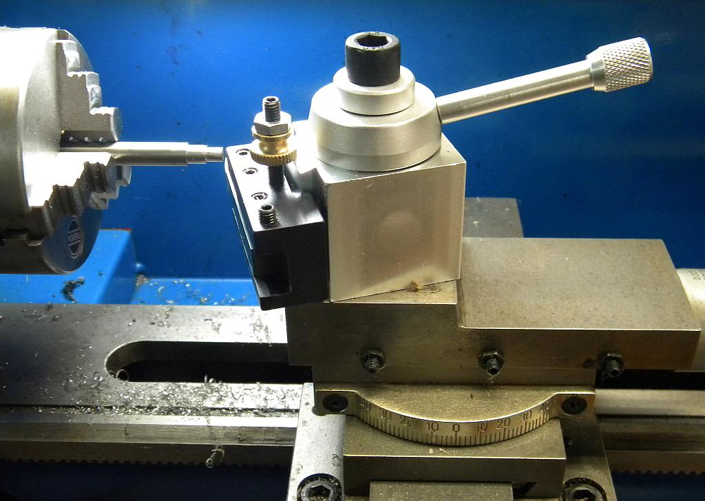
Random Quote

“When even one "American" -- who has done nothing wrong -- is forced by fear to shut his mind and close his mouth, then all Americans are in peril.”
-- Harry S Truman

How to Grind and Use the 'Contrary Finishing Tool'

This excellent article was written by Bob Bickerton, a new contributor to Machinistblog.com. It was originally published to the files section of the Yahoo 7x12minilathe discussion group.

The slowest feed rate on the Mini-lathe is about .004 in/revolution. This is fine for many applications but when you want a nice, smooth turned finish the slowest rate isn’t slow enough. You can set the knife tool to ‘rub’ and that helps sometimes. And, there have been modifications published that allow the slow feed to be reduced, but all require building something for the lathe. Here’s another option that only requires one to grind a HSS tool blank to a different shape. It’s a “Contrary Ground Finishing Tool” described by Frank Burns on page 58 of the Jul-Aug. 1997 issue of Home Shop Machinist magazine. Here’s how I do it.

I turn the OD of the work piece with the usual ‘knife tool’ until it’s about 10 thousandths oversize. Then I mount my ‘finishing tool’ and adjust the cross feed to just skim the surface (about a thou or so). Note the cross slide in feed dial reading. Measure the OD and set the cross slide to remove about half of the still oversize work piece. Measure the OD again, and if everything went well you should have removed half the oversize. If so, set the cross slide to remove the remainder and, presto, you have a nicely turned finish on specification size. If the first pass removed a little more or a little less than half, make an appropriate adjustment before the final cut.


Here’s a picture of some EMT conduit mounted in the chuck of my Cummins 7x12. EMT is welded steel tube and difficult to finish, at least for me. The welded seam can be harder than the surrounding area making it difficult to get a good, smooth finish. The front has been machined with my usual knife tool. The finish doesn’t look to bad but it is rough to the touch.

Here’s that same piece after using the ‘Finishing Tool.’ Hard to tell from the picture but the finish is very smooth to the touch. Because the tool cuts on the front it doesn’t need to be exactly on center height. You can’t cut up to a shoulder because of the geometry.

How to Grind and Use the ‘Contrary Finishing Tool’

Because of the high level of interest in this subject, I decided to show how I grind the tool and then show it in use. Here’s how I do it.

Continue reading → How to Grind and Use the ‘Contrary Finishing Tool’

Free Plans: Ball Turning Tool Post for the 7x Mini-lathe

I want to tell you about Ralph Patterson’s free plans for a ball turning tool post that will fit a 7-by-whatever mini-lathe, and show you how he used it to fix a broken shower head.  I’ve also included a YouTube video that shows a similar tool post being used to make

Continue reading Free Plans: Ball Turning Tool Post for the 7x Mini-lathe

A Homemade DRO for the 7x Mini-Lathe

The DRO uses an inexpensive digital dial indicator that's held in place on the apron with powerful rare-earth magents. The stop clamps to the top of the cross-slide and presses against the indicator's plunger, which measures the movement of the cutting bit.

This article describes how I added an easy-to-make DRO (Digital Readout) to the cross-slide of my 7×12 mini-lathe.  It uses an inexpensive digital dial indicator that I bought from Harbor Freight for about $25.  It works very well and you won’t have to drill any holes in your lathe or disassemble it to install it.

I’ve rarely seen a picture of a mini-lathe with a home-made DRO on it (or any kind of DRO), even though they seem to be fairly common on mini-mills.  The ones for mills are usually made from inexpensive digital calipers or scales.  I considered using them on the mini-lathe but rejected the idea because there is very little room to put them where they won’t be in the way.  They will probably collect piles of swarf, the displays are also likely to be difficult to read and the buttons will probably be located where they will be awkward to push.

Using a digital dial indicator eliminates or minimizes those problems, although it is not a perfect solution.  You’ll have to read the display and buttons upside down, which is not really much of a problem because they’re quite large and easy to read.

The indicator has a range of just 1-inch, but my design uses an adjustable bracket that will let you engage the DRO where ever you need it.

The DRO has two parts.  The first is the indicator holder.  It’s an aluminum bracket that attaches the dial indicator to the apron using very powerful rare-earth magnets.  The magnets are located where they are unlikely to attract steel or iron chips.  The second is a stop that clamps to the top of cross-slide and makes contact with the point of the indicator.

The stop can adjust two ways so it can always be made to press against the indicator’s probe, no matter the diameter of your work piece.  You just slide it along the top of the cross-slide until it makes contact with the tip of the indicator, which is mounted on the apron.  I thought there might be situations, like when working on a very large diameter workpiece, where the stop might not be able to contact the indicator.  So I also added an adjustable rod to extend its reach.  I now know it’s not needed, although it might if you adapt my design to another lathe.

The DRO does not interfere with the lathe's controls and you can easily remove it in seconds if you want.

The DRO works very well and it has really improved my productivity.  I no longer have to keep stopping to measure how much more metal I have to remove, or keep track of how much I’ve turned the cross-slide knob and  then calculate how much more I need to cut.

Most of the time the DRO and the cross-slide dial are in complete agreement, or at least within five ten-thousandths (.0005), which is the resolution of the DI.  When they disagree it’s usually because of backlash.

However, I was surprised to find that they would sometimes consistently disagree by forty-five thousandths, and it wasn’t due to backlash.  I haven’t fully investigated the cause yet, but I’m pretty sure it’s going to turn out to be axial end play in the leadscrew.  It’s a pretty common mini-lathe problem caused by a gap between the head of the leadscrew and the flange it is suppose to turn against.  The most common fix is to make a small washer to fill that gap.  It’s not really an issue and I’ve learned to trust the DRO.

Construction

This a prototype and not a finished design.  I am hoping that others who are smarter and have better machining skills will think of ways to improve it and then share their ideas.  That’s why there are no plans for it yet (a shortage of spare time and poor CAD skills also has something to do with it).  So, until I get some plans drawn, I hope my photographs will allow you to make your own if you want to.  Please let me know if you have any questions and I’ll do my best to answer them.


Continue reading → A Homemade DRO for the 7x Mini-Lathe

Lever-Operated Tailstock Cam Locks – Three Well Known Designs you Can Build and a Kit you Can Buy

It has been more than a year and a half since I bought my 7×12 mini-lathe and I finally decided I needed to get serious about building or buying a cam-operated tailstock lock for it. A lever-operated lock is probably one of the most popular modifications for the mini-lathe because it increases your productivity by eliminating the need to find a wrench and turn a nut every time you want to move the tailstock.

Much of my delay has been because of my indecision about which of the various designs floating around the Internet is the best.  So I started sorting through my collection of bookmarks and found that I needed to compare three well-known designs I could make, plus a kit I could buy and install easily. 

Continue reading → Lever-Operated Tailstock Cam Locks – Three Well Known Designs you Can Build and a Kit you Can Buy